


Overview
Chermay's optical transceiver portfolio includes 10G SFP+, 400G QSFP-DD and 800G OSFP/QSFP-DD modules. Optical power, wavelength, data rate and temperature limits are defined by the exact product specification and interface rather than one set of values for all modules.
Our Quality Control Process
Incoming Component Inspection
Incoming optical assemblies, ICs, PCBs, connectors and housings are checked for identification and visible defects before assembly.
In-Process Assembly Inspection
Assembly checks cover solder condition, component placement, mechanical fit and optical connector condition at designated workstations.
Module Configuration Verification
Product markings, encoded identification and firmware configuration are matched to the specified rate, reach, interface and host-coding variant.
Optical and Electrical Functional Checks
Transmitter, receiver and host-side functions are checked against parameters specified for the corresponding module model.
Link-Level Function Check
Link-up, status reporting and applicable port modes are checked using a matching test setup. Host interoperability qualification is a separate activity.
Final Inspection and Release
Finished modules are checked for label consistency, connector protection, external condition and packaging before release against the applicable criteria.
Optical & Electrical Performance Testing
Transmitter Power and Wavelength
An optical power meter measures average transmitted power; an optical spectrum analyzer establishes center wavelength and related spectral characteristics. For parallel or wavelength-multiplexed designs, the specified per-lane or per-channel limits take precedence over aggregate optical power.
NRZ and PAM4 Signal Quality
NRZ optical interfaces use measurements such as eye characteristics and extinction ratio where specified. High-speed PAM4 interfaces can require outer optical modulation amplitude (OMAouter) and transmitter and dispersion eye closure for PAM4 (TDECQ). TDECQ results depend on the prescribed reference receiver, equalization and test pattern.
Receiver Sensitivity and Overload
Receiver sensitivity is evaluated with a controlled optical signal and variable attenuation while error performance is monitored at the defined threshold. Overload evaluation checks the upper optical input level at which the receiver must still operate within specification. Both depend on the interface and test conditions.
Bit Error Rate and FEC
A bit error rate tester applies a known data pattern and compares the received stream with the expected bits. For PAM4 links using forward error correction, pre-FEC error measurements and corrected link performance are different criteria. The applicable standard or product specification defines which result is used.
Host Interface and Digital Diagnostics
Electrical checks address the module supply and host-side signaling requirements. Chermay's published 10G SFP+ range lists DDM support, while the 800G OSFP/QSFP-DD series lists digital diagnostics and a CMIS management interface. The interface exposes operating data such as module temperature, supply voltage and optical power.
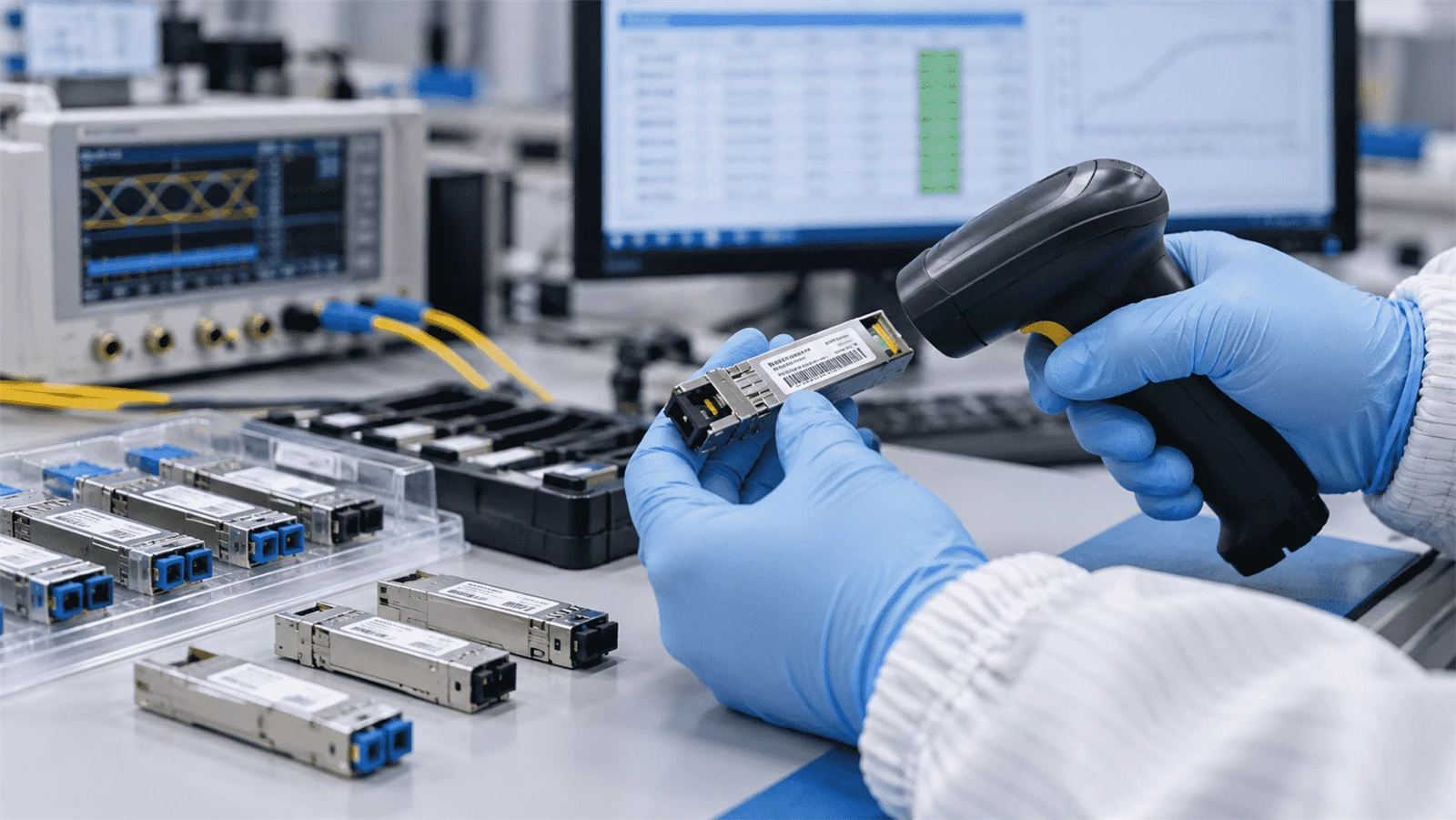
Quality Management & Traceability
Product Identification and Records
Module part number, optical interface, form factor, label and encoded identification data distinguish individual product variants. Where batch- or serial-linked inspection records are retained, those identifiers provide a route to the corresponding measurement and release information.
Acceptance and Nonconformity Review
A measurement result is evaluated together with its test conditions and the applicable specification limit. Results outside the required range call for nonconforming-product disposition; corrective work must be followed by verification of the affected characteristic before acceptance.
Frequently Asked Questions
How is a test requirement linked to a specific transceiver part number?
-
The part number identifies the data rate, interface, optical reach, wavelength or lane configuration and operating grade. These fields determine which product limits and test conditions apply; a shared package type does not imply identical optical specifications.
What information helps investigate intermittent optical link errors?
-
Useful evidence includes the module part number, host model, firmware version, link rate, FEC setting, optical diagnostic values, error counters and fiber-connection details. The operating temperature and the time of the fault help distinguish intermittent link conditions.
Why can a DDM or CMIS power reading differ from a power-meter result?
-
DDM and CMIS report values estimated by the module electronics. An external optical power meter is a separate measurement reference. Comparisons require a consistent operating state, measurement point and calibrated instrument.
Does an operating-temperature grade confirm that every unit completes burn-in?
-
No. An operating grade defines a specified service range. Powered burn-in, thermal cycling and storage testing are separate procedures with their own temperature profile, duration and sample plan.
What should an optical test or host-compatibility report identify?
-
The report should identify the part number and revision, test conditions, measured parameters, acceptance limits and results. Host-compatibility results should also name the host hardware, software release, port mode and FEC configuration. Report scope and availability are product- and order-specific.